Power Analysis and Optimization
PowerPro offers the best-in-class capabilities to develop low-power, energy efficient systems by combining fast and accurate power estimation with industry leading power optimization. With its rich set of features and metrics, it enables designing for low-power throughout the RTL design cycle.
Key Challenges
Power is the most untapped avenue to bring your product to the next level. Power optimization can extend your products daily, weekly, and lifetime use. PowerPro allows for RTL and Gate Level Analysis. Explore this page and the main PowerPro directory to learn the solutions to make this happen.
Power Estimation
Power Estimation is important as modifications need to be made quickly and verified. Accuracy, accessibility, and power follow-ups are all needed for a concise workflow. Click below to explore how PowerPro tackles this challenge.
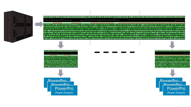
SoC Power
SoC power presents the formidable challenge of design size and extensiveness of real workloads. PowerPro explores a full chip power profile for billion+ gate design, making large designs manageable.
Glitch Power
Glitch power can be a significant contributor to a design's dynamic power. The emergence of intensive processes like AI can have glitch power account for 40% of dynamic power.
Power Optimization
Designing for low-power can offer significant challenges to RTL designers as it requires not only low-power expertise but also significant effort to find and fix power issues early in the RTL design process.

Best Practices to Overcome Low-Power Design Challenges
These practices are essential for realizing low-power, energy efficient designs and can help you meet power budgets, mitigate potential reliability issues arising out of power and discover thermal issues early to take corrective action. NXP will present their perspective on applying these techniques. You will learn how our low-power design platform helps simplify low-power design for RTL designers.

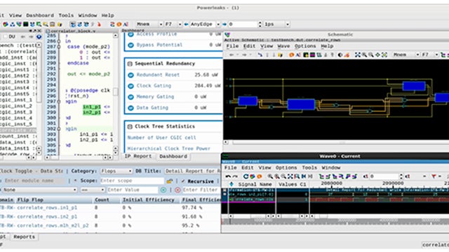
PowerPro Power Analysis & Optimization Platform
PowerPro offers the most comprehensive set of features to RTL designers to “design-for-low-power”. It offers power analysis for both RTL and gate-level designs, early power checks to quickly find power issues during RTL development and clock and memory gating to optimize the design for power.


PowerPro Power Analysis & Optimization
From AI/ML, CPU/GPU, Modems to IoT, learn how Siemens' PowerPro helps meet power budgets and deliver energy efficient IPs by enabling low-power RTL development throughout the design cycle and qualify IPs for low-power.
